Additive Manufacturing - FYI

SKĒM-INC: 3D PRINTING TECHNOLOGY #SLS v #SLA v #FDM What is the Difference?

Difference of FDM, SLA and SLS Pint Textures

Explaining the different nuances of some Additive Manufacturing (3D printing) technologies.

This article will run through three of what are considered to be the most popular 3D printing methods.  If you have questions, comments, or would just like to chat about 3D printing, feel free to get ahold of us through the comment section at the bottom of this page or through one of our social media outlets.

SLS (Selective Laser Sintering)

For anyone looking to make long-term, mechanically-sound functional parts, SLS is about as good as it gets.  The SLS (Selective Laser Sintering) process is used primarily in industrial applications as the machines are typically outside of the justifiable price range for most small businesses and DIYers.  That being said, typically this method produces some of the best isotropic mechanical properties achievable in 3D printing.  However, it unfortunately is not the fastest process.  In SLS, a thin layer of powder is dispersed onto the build platform usually ~.1mm or less in height depending on the application and machine.  The powder material is sintered by the laser, and the build plate then lowers by the specified layer height (~.1mm).  A new layer of powder is then redistributed and is then sintered to the previous layer.  Figure A below shows a simplistic example of a SLS machine.  While figure B shows  a close up view of the powder pellets melting into a solid layer. 

Figure A

Figure B

This method of printing is advantageous for a couple of reasons. For instance, because the powder that surrounds the part essentially holds the part suspended in place, it is capable of producing parts without the need for a support structure.  This also allows for the entire build volume to be packed with parts very close together.  In many cases, multiple parts of an assembly can be produced fully assembled right out of the printer.  Below I have embedded a short YouTube video from my channel SKĒM-INC to subscribe click  here!

SLA (Stereolithography)

 In the SLA (Stereolithography) process, the material actually starts as a photosensitive liquid resin.  The liquid resin gets hit with UV light causing a chemical reaction at which point the resin begins to harden.  In most industrial cases this is done with a laser.  However, the MSLA (Masked Stereolithography) version of SLA is done with a Matrix of LED lights behind an LCD screen.  The images below are especially helpful to highlight and explain these differences visually.  In each image, the grey on the top represents the build plate which holds the part (upside down) as it is printed.  The blue represents the liquid resin and the yellow is the 405nm light or laser.  Take a look at the image to the right you will see what to me looks like the top view of a basketball hoop…  That is the cured resin (final part).  

SLA v DLP v MSLA  image credit: Formlabs www.formlabs.com

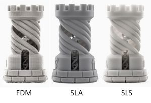
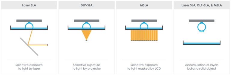
As you can see, each system shown above is able to produce the same part and all are using light to cure a part in height/layer of ~.02-.3mm at a time.  However, MSLA, is the version that has exploded on to the DIY market within the last few years.  This is because of how inexpensive it is to throw some LED lights under a vat of resin.  Additionally, it is also much faster since you can cure the entire layer at once.  No matter how big the part or how many parts are on the build plate, each layer will take the same amount of time.  This is not the case for both the SLA and SLS methods since they use a laser to trace a 2D layer.  MSLA simply displays a 2D sliced image of the layer it is curing.  With MSLA, most layers take ~8 seconds or less.
When designing a part for SLA printing, there is not much that will need to be changed from one version to the other.  All SLA methods typically require support structures in order to hold the part during the print, which causes a bit of post processing to remove the support structures as well as dimples that may be left over from these supports.  Depending on the surface finish and part quality you are looking to achieve, some additional sanding and painting may be required.  If you see a 3D printed miniature action figure chances are it has been SLA printed.  The ultra fine details you can get topped off by the paintable nature of the resin are what makes SLA the more likely choice.  Below is another great video I found on YouTube from Adafruit Industries.  If you want to see the amount of detail that can be achieved on your parts, be sure to watch until after this miniature space ship gets cleaned!  Check out how tiny those details are!
To visit Adafruit Industries’ YouTube channel click on the link below: 
Click here to read a more in depth article on the different SLA printing techniques.

FDM (Fused Deposition Modeling)

Generally, when you bring up 3D printing to someone, FDM (Fused Deposition Modeling) is the process they are most likely to be familiar with.  However, use of this method does not produce the same detail nor isotropic mechanical quality of parts that would otherwise be achievable with SLS and SLA Additive Manufacturing methods.  FDM Process creates parts that are Anisotropic.  Anisotropic parts can be good, bad, or might not matter at all depending on the application.

That being said, FDM can boast many positives.  For instance, FDM is safer, easier to use, and makes it much easier to handle materials.  Typically, FDM uses a Filament Spool.  This is a 1.75~3mm diameter extrusion that is wrapped in 1-5kg spools of material.  There are no harsh chemicals used in the process, and in most cases not even a bad smell.  It is basically functioning like a hot glue gun.

Hot Glue Gun  image credit: Gorilla Glue www.gorillatough.com

In the FDM process, the spooled material gets threaded through the machine and is eventually pushed into a heated block causing it to melt as it nears the exit of the nozzle.  The melted filament is then deposited on a build platform eventually creating a layer of the part. This method generally ranges from the .1~.8mm layer height. Below is an illustration that also depicts the supports in red.  It is possible for this support material to be different from the part material if you have at least a dual extruder machine.  In some cases, the support material can even be soluble allowing for very easy removal of the supports after the part is completed.

The principle of FDM method [Thai3dprint 2012]

Many FDM machines on the market today have a heated build platform.  This helps the material adhere to the surface of the build plate and reduces warpage etc.  Common materials that are used in FDM printing consist of PLA (Polylactic Acid)ABS (Acrylonitrile Butadiene Styrene)TPU (Thermoplastic Polyurethane) etc. It should be noted that there are seemingly limitless other varieties and blends of materials that have already been developed as FDM has risen to fame. This method is by far and away the best starting point for most 3D hobbyists and businesses (including myself).  This video from i.materialize is a time lapse video demonstration of the technology.

To visit i.materialise  YouTube channel click on this link below:

https://www.youtube.com/c/imaterialise/videos

Please leave a comment below with any questions or suggestions to make our future posts even better!

Leave a Reply

Your email address will not be published. Required fields are marked *